HTX100 Alignment of P.L.L. and Carrier Oscillator Portion
|
|
|
|
|
|
|
S.S.G.:29MHz |
|
Connect a DC voltmeter to TP 301.
Adjust L302 for 4V +/-0.1V reading on the DC voltmeter. |
|
|
|
|
Connect an oscilloscope to TP302
Adjust L303 for maximum reading on the oscilloscope. |
|
|
|
|
Connect a frequency counter and the oscilloscope to TP303.
Adjust L313 for 10.695 MHz +/-10Hz reading on the frequency counter. |
|
|
S.S.G.:29.699MHz |
|
Connect an oscilloscope to TP307.
Adjust L312 for maximum reading on the oscilloscope. |
|
|
|
|
Connect a frequency counter and the oscilloscope to TP307.
Adjust L321 for 22.0009 MHz +/-10Hz reading on the frequency counter. |
|
|
|
|
Adjust VR303 for 22.0000 MHz +/-10Hz reading on the frequency counter |
|
|
|
|
Connect the oscilloscope to TP305
Adjust VR302 to obtain the waveform as shown on the Fig 1. |
|
|
|
|
Connect the oscilloscope to TP306
Adjust VR301 to obtain the waveform as shown on the Fig 1. |
|
|
|
|
Connect a DC voltmeter to TP 303.
Adjust L317 for 5.5V +/-0.1V reading on the DC voltmeter. |
|
|
|
|
Connect a DC voltmeter to TP 303.
Check if voltage is more than 3V at TP303. |
|
|
|
|
Connect a frequency counter and the oscilloscope to TP304.
Adjust L321 for 38.695 MHz +/-20Hz reading on the frequency counter |
|
|
S.S.G.:29MHz |
|
Connect a frequency counter and the oscilloscope to TP304.
Adjust VR304 for 38.695 MHz +/-20Hz reading on the frequency counter |
|
|
S.S.G.:29MHz |
No Alignment | Connect a frequency counter and the oscilloscope to TP301.
Check if the frequency is 38.695 MHz +/-1.0 - 2.0 kHz when turn the RIT volume to fully clockwise to counterclockwise.Taken from the RS Service Manual # 19-1101 by Rogerbird |
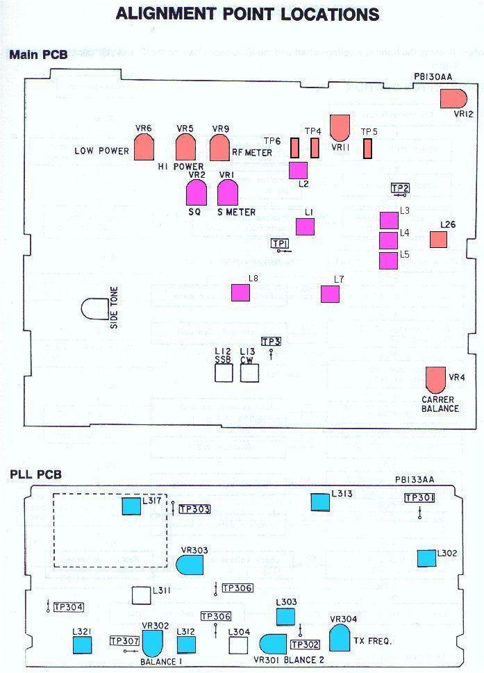
Click Here to see Alignment layout
HTX100 Alignment of Transmitter Portion
Taken from the RS Service Manual #19-1101 By Rogerbird
|
|
|
|
|
|
|
No Modulation |
|
Remove the B001 (PB-100) from the Main PCB.
Connect a DC Ammeter (+) to TP6 (-) to TP5. Adjust VR11 for 50mA reading on the DC Ammeter. |
|
|
|
|
Connect a DC Ammeter (+) to TP6, (-) to TP4.
Adjust VR12 for 50 mA reading on DC Ammeter. |
|
|
OSC 2: 2400Hz S1,S2: ON Mode: SSB |
|
Disconnect the DC Ammeter. Reinstall the B001 to the Main PCB.
Connect a RF Power meter to the antenna jack and then, connect a RF SSVM, and oscilloscope across a RF dummy load to the RF power meter. Adjust L26 for maximum reading on the RF SSVM. During this step, set the AF S.G. so that the output is less than 20Vp-p. Repeat this step two times. |
|
|
|
|
Adjust level of OSC1 and OSC2 for 30 mV reading on the AF SSVM, then adjust VR5 for 36Vp-p reading on the oscilloscope. |
|
|
Control (Low Power) |
|
Adjust level of OSC1 and OSC2 for 30 mV reading on the AF SSVM, then adjust VR6 for 16Vp-p reading on the oscilloscope. |
|
|
|
|
Adjust VR4 so that the carrier leakage at SSB and CW becomes minimum and almost equal. |
|
|
|
|
Adjust level of OSC1 and OSC2 for 30 mV reading on the AF SSVM, then adjust VR9 so that the "9" LED just lights on. |
|
|
No Modulation |
|
Connect a AF SSVM across a dummy load (8 Ohm) to EXT jack.Connect a key switch to the Key jack. With Key switch ON, adjust VR13 for 0.2V reading on the AF SSVM. |
|
|
KEY SW: ON |
|
Check if the RF power level is 23 ~ 29W reading on the RF power meter. |
|
|
(Low Power) Pull RF Gain Control |
|
Check if the RF power level is 3 ~ 7W reading on the RF power meter.
Copied By Rogerbird from the RS Service Manual #19-1101 |
Click Here to see Alignment layout
HTX100 Alignment of Receiver Portion
Taken from the RS Service Manual #19-1101 By Rogerbird
|
|
|
|
|
|
|
L7 and L8 |
Alignment for Sensitivity
Adjust coils for maximum reading of the AF SSVM. (During this step, set the Standard Signal Generator attenuator so that the standard output is less than 0.5W (2v/8ohm)). |
|
|
|
|
|
Alignment for Squelch
Set the output of the Standard Signal Generator attenuator to 1mV and squelch to maximum. Adjust VR2 so that squelch just breaks. |
|
|
|
Alignment of S-Meter
Set the output of the Standard Signal Generator to 100uV, no modulation. Adjust VR1 so that "9" LCD just lights on. |
|
|
|
|
|
Set the level of the Standard Signal Generator to 2uV, then adjust L1 for maximum reading on the oscilloscope. Connect the oscilloscope to TP1. Copied from the RS Service Manual #19-1101 By Rogerbird |