This mod was originally written by M.T. Stacey, KC4HGH, in an article published in "73 Amateur Radio"
of September 1989 on page 48. There was also an Update in "73 Amateur Radio" of November 1989 on page 76.
Copy of update by M.T.STACEY, KC4HGH
I sincerely apologize to everyone who have been inconvenienced by the original results printed.
This mod was originally written by M.T. Stacey, KC4HGH, in an article published in "73 Amateur Radio"
Copy of update by M.T.STACEY, KC4HGH
I sincerely apologize to everyone who have been inconvenienced by the original results printed.
Update thanks to: R, Madaire, Ottawa, Ontario, CANADA.
------------------------------------------------------------------------
Due to a technical error, innacuracy in my original test setup, the PEP power levels on page 48 of Sept.
"73 Amateur Radio " were erroneous. After revamping the test bench equipment, and testing the new
wattmeter against a Bird 43, the findings are as follows, In modified radios, 2-3 watts carrier, and 10-12
watts PEP average increase over the stock peaked-out radios. Therefore, the original goal was reached,
i.e. more power with better audio and less stress in the RF output section.
With regards to all, M. T. Stacey.
1). Remove the top and bottom covers.
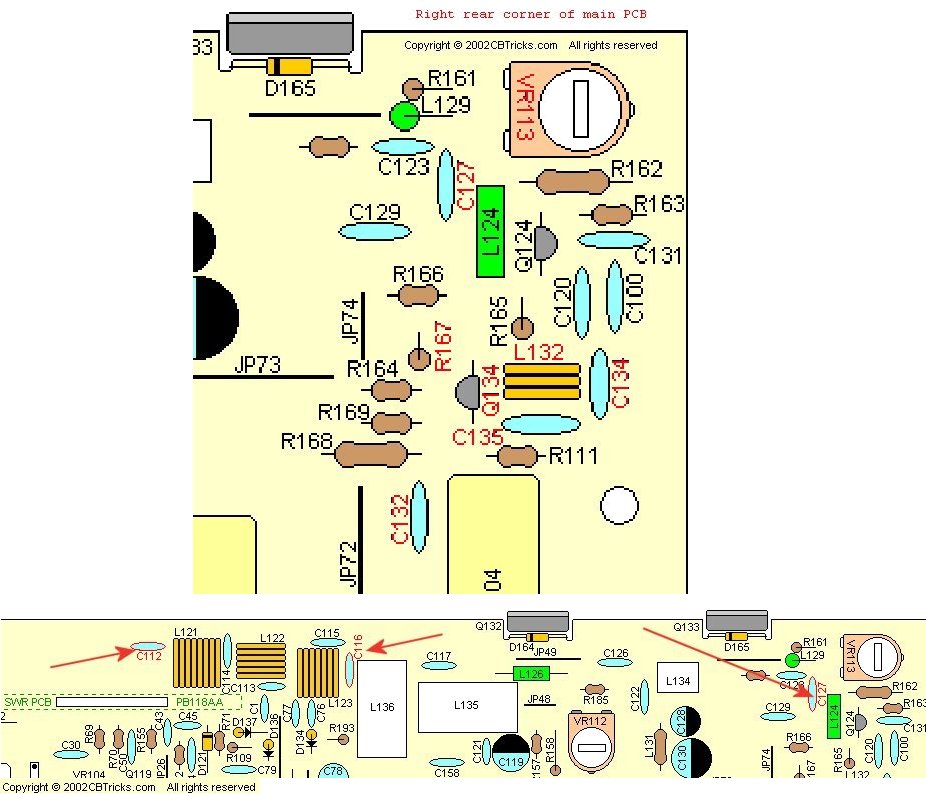
2). Locate and remove Q132 & Q134.
3). Replace Q134 with an ECG340 or TCG340.
WARNING!!! The leads of the two transistors are exactly opposite of each other.
[2SC2086 = BCE ; ECG340 = ECB.]
4). Replace Q132 with an MRF497. ( Be sure to use heat sink compound. )
5). Remove C132. ( no replacement)
6) Remove C112 & C116.
7). Replace C112 with an 82pf capacitor, But put the new Capacitor on the bottom of the PC board.
8). Replace C116 with an 100pf capacitor, But put the new Capacitor on the bottom of the PC board.
Click here for the Board
Layout locations for the Capacitors in HR2510
Click here for the Component
Layout with Cross reference for the HR2600
9). Connect power to the radio, and following the alignment procedures, adjust the bias of Q132 to
80mA +/- 5mA by adjusting VR112.
[To adjust the bias of Q132: Remove the B002 (PB-100) jumper board from
the Main PCB.
Connect a DC Ammeter (+) to TP4, (-) to TP3.
With the radio on USB, Adjust VR112 for 80mA +/- 5mA on the DC Ammeter.
After the adjustment is complete, Reinstall the B002 (PB-100) jumper board.]
10). Inject a two tone signal into the microphone of the radio while transmitting into a dummy load.
Set VR104 (ALC) for maximum output..
Retune VR107 (AM /FM carrier level) for Maximum.
Retune VR103 (CW carrier level) for Maximum
11). Again inject a two tone signal into the microphone of the radio while transmitting into a dummy load.
Spread or contract coils L121 & L123 for the highest power out in the
center of the band.
12). Replace the covers and the screws, you should now have between 50 and 100 watts on SSB.
of September 1989 on page 48. There was also an Update in "73 Amateur Radio" of November 1989 on page 76.
------------------------------------------------------------------------
Due to a technical error, innacuracy in my original test setup, the PEP power levels on page 48 of Sept.
"73 Amateur Radio " were erroneous. After revamping the test bench equipment, and testing the new
wattmeter against a Bird 43, the findings are as follows, In modified radios, 2-3 watts carrier, and 10-12
watts PEP average increase over the stock peaked-out radios. Therefore, the original goal was reached,
i.e. more power with better audio and less stress in the RF output section.
With regards to all, M. T. Stacey.